ELECTRICAL AND
COMPUTER ENGINEERING
![]()
1.
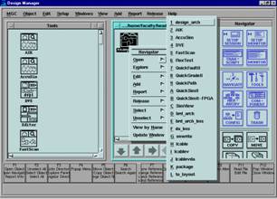
In the Design
Manager file window select “example1”
2.
Right click to
get pop-up menu
3.
Move pointer
to "open"
4.
Select #3
AccuSim
5.
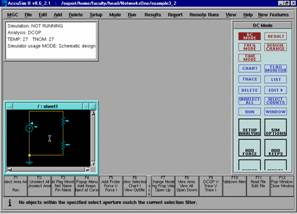
![]() Once AccuSim opens expand the screen and select the screen
titled /:sheet1
Once AccuSim opens expand the screen and select the screen
titled /:sheet1
6.
Perform a
"View all" by holding down center button and drawing a line from
lower right to upper left.
7.
Select
"Setup Analysis" from the button panel on the right of the screen
![]()
![]()
![]()
![]()
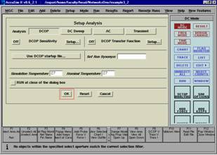
8.
Select
"DCOP" (DC operating point) don't change anything else and click OK.
9.
Select
"Run" from the button panel on the right of the screen. A screen titled "Add Keeps" will
pop up, choose "All" and click "OK"
10. Note that the button panel has changed from the "DC
Mode" to the "Result" options.
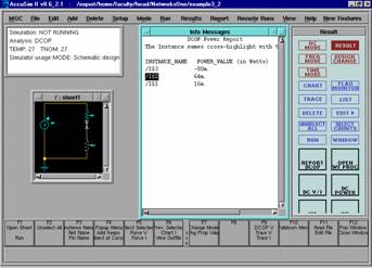
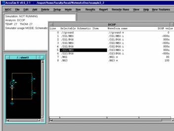
11. Select "Report DCOP". Now on your circuit, select the point (not
the wire) between voltage source and the wire that connects it to ground.
12. Note that when you do this a line in the DCOP screen is
highlighted; this indicates that the value of current into the selected point is given by the DCOP value on that line.
13. On your schematic, select the wire that connects the voltage
source to the 25K W
resistor this causes the line of text in the DCOP report that gives the voltage
value at the wire to be highlighted.
Play with this feature by now selecting lines in the DCOP window and
note that the corresponding wire or point is selected in the schematic
(remember that you can always unselect by using the function key, F2)
14. Close the DCOP window.
15. Select "DC Power" from the button panel.
16. On the pop-up screen select "All" and then click
"OK"
17. Note the if you select either a component on your circuit or
a line in the DC Power Report both will be highlighted so that you will know which
power dissipation value is associated with which component.