ELECTRICAL AND
COMPUTER ENGINEERING
![]()
When the instructions
say to type “something” – don’t type the “
“, just type what is inside the
“ “.
To begin, log on to galaxy.
1.
Open a
terminal window / console window (right click>Tools>Terminal)
2.
Use the
Mentorgraphics directory that you created in the Design Manager Tutorial. In the terminal window type “cd
your_directory_name”
3.
Next, type
"dmgr_new &" and return, the Design Manager Window will open as
shown below.

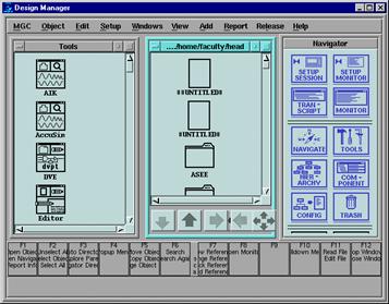
4.
Expand the
Design Manager window to fill the screen
5.
Left click on
the Tools window then right click and choose "Update Window"
6.
Repeat above
in the Files window to the right of the Tools window
7.
Left double
click on your Mentorgraphics folder if you did not change directories before
invoking Design Manager
8.
Left click on
the Tools window and double click on the design_arch icon
![]()
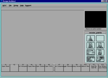
9.
Expand the
Design Architect window to fill the screen
10.
Left click on the
"OPEN SHEET" icon in the "session_palette" window
11.
A pop-up
window will appear called "Open Sheet" and it will have a line window
called "Component Name"
12.
The
"Component Name" space is the ONLY one that you will enter any text
into.
13.
You should see
your file path in this window [/export/home/students/your login id].


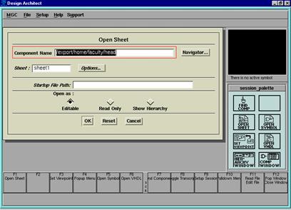
14.
Move your
pointer to the "Navigator..." window and select it
15.
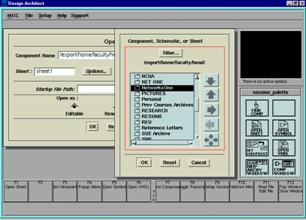
Find your Mentorgraphics folder and
select it (but don't double click on it), select "OK"

![]()

16.
Move your
pointer over the "Component Name" window, the text will be selected
and a red-line box will be drawn around the window.
17.
Single left
click in the window and your pointer will become a text cursor.
18.
Type
"/example1" , be sure that "Editable" is selected in the
"Open as:" section of the window and select "OK" at the
bottom.
19.
A drawing
screen will appear where you will draw your circuit.
![]()
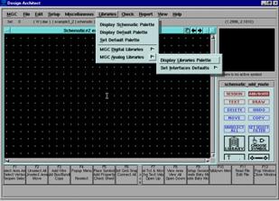
20.
Select the
"Libraries" pull down menu.
21.
Left click the
arrow next to "MGC Analog Libraries" and then select "Display
Libraries Palette".
22.
The "MGC
Analog Libraries" palette will appear at the right of the Design Architect
screen.
23.
![]() Select
"Generic Parts".
Select
"Generic Parts".
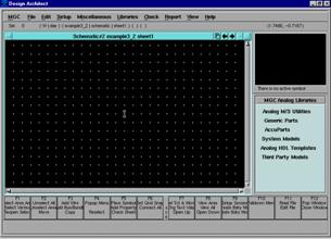
24.
For example1
(see last page) we need 2 resistors and a voltage source.
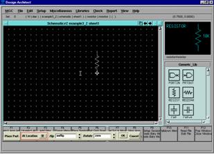
25.
Select the
icon labeled "RESIST" note that a resistor pops up in the screen
above the palette.
26.
Move the
pointer over the drawing screen and note that a white, dashed-line resistor
appears at your pointer
27.
To place the
resistor, left click on the drawing screen
28.
Note that the
resistor is still drawn with a white dashed line, this means that it is
selected
29.
To un-select
the resistor, depress the function key F2.
![]()

![]()
![]()
30.
Note that the
resistor value is 10K, we want our resistor to be 25K W.
31.
Place the
cursor/pointer over the "10K" and type "shift+F7" a
"CHA PR VA" window will pop-up at the bottom of your screen.
32.
Type
"25K" in the "New Value" window and select "OK"
33.
Repeat the
above process to place a 100K W resistor below the 25K W one.
34.
![]()
![]() Return
to the "Generic_Lib" palette and find the voltage source by scrolling
through the icons, it is called "V-SCR"
Return
to the "Generic_Lib" palette and find the voltage source by scrolling
through the icons, it is called "V-SCR"
35.
Place the
voltage source (position it to the left of the resistor with some space between
them for wiring), unselect it and change its value to "100"
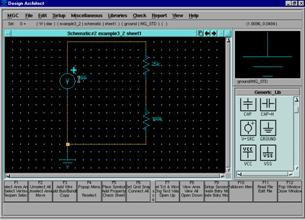
36.
We must
explicitly provide a ground point for our circuit (this is assumed in most text
book problems).
37.
Find the
"GROUND" icon in the "Generic_Lib" palette, select it and
place it near (but not attached to) the negative terminal of the current
source.
38.
In the
"View" pull down menu you will find the "Zoom" commands,
try "View All", ZOOM-in, Zoom-out, etc. until you see how to use
them.
39.
Get all four
of your components on the screen with room to work.
40.
To wire the
circuit together, move the pointer to the drawing screen, make sure the screen
is selected and type the function key, "F3"
41.
A small white
cross will show up under your cursor.
42.
To draw a
wire: single left click on the starting point, single left click to make a
turn, double left click at the ending point.
43.
When you are
done wiring the circuit cancel the "ADD WR" window at the bottom of
the screen and unselect your circuit (F2).
44.
Finally, we
will check our circuit for errors and save it.
45.
Select the
"Check" pull-down menu, select the arrow next to "Sheet"
and then choose "With Defaults."

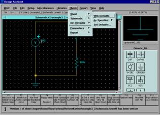
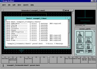
46.
A screen will pop-up
that should show zero errors and zero warnings.
47.
Close this
window by double left clicking on the small box in the upper left hand corner.
48.
![]()
Select the "File" pull-down
menu, choose the arrow next to "Save Sheet" and choose "Default
Registration."
49.
Close your
schematic sheet, close Design Architect and return to Design Manager.
Example1