Networks I - Lab Section 6: Mondays –
Lab Assignment 6 - due:
next Monday
NETWORKS I LAB #6 - ASTABLE MULTIVIBRATOR
Lab Designed By: Jason Berenbach (ECE Senior 2004)
BASIC CONCEPTS:
This lab should be completed after going over RC circuit analysis knowledge for designing and testing circuits. Teams should also already understand basic operations of an Op Amp. If you have ever looked at the equipment in the lab then you probably will have noticed the signal generator (HP33120A). It has lots of different outputs and some of the symbols above the outputs show different kinds of waves. One selection shows a sine wave and the other looks like a square wave.
(Problem #1)
Hook up the signal
generator (HP33120A) to the oscilloscope (HP54645D) and get a signal similar to
the one below on the oscilloscope: (Choose any frequency you want and you can
use input A1 or A2. The signal generator has as a max capability of producing
15MHz)
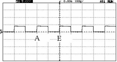
Over the background of the oscilloscope (also called a CRO -
short for Cathode Ray Oscilloscope) you can see black / grey horizontal and
vertical graduations. They represent the horizontal time base settings and the
vertical amplifier settings. In the above picture, which is an example, the
vertical amplifier represents 5V per division and the horizontal time base
setting represents 100 micro-seconds. To
calculate 1 full period, which means from point A all the way to point E (peak
to peak), is 2 increments on horizontal or ![]() .
. ![]() ; this would translate to
; this would translate to ![]() or
or
![]() .
.
The square wave is very useful because is has HARMONICS. Square wave signals are full of harmonics that is say that we have a 5 kHz signal. We get a lot more then just the 5 kHz signal but also we get its multiples like 10, 15, 20, 200,550 kHz, etc… forever until the signal becomes too weak to see. This can be a useful tool when troubleshooting audio amplifiers that use high frequencies like a radio.
(Problem #2)
Other then 5 KHz, select 5 frequencies between 100 Hz and 5 MHz and
confirm that it is shown correctly on the oscilloscope. Remember the values of
each increment on the scale can be shown differently, so the wave may not look
exactly like the previous figure. Show your calculations and specify values of
y and x axis!
For now, the signal generator was used just for testing, but now we will focus on how the square wave is generated. A square wave signal generator is also called a “Multivibrator” and we will now look at how to build one. Of course the simplest way to do it would be to have a circuit with a switch, and constantly turn the switch on and off because of its digital behavior. That means either it’s a 1 or a 0. In the previous case the example used was 0 V and 5 V. But since it’s not humanly possible to turn a switch on and off 5000 times a second, using a circuit is the best method.
ASTABLE
MULTIVIBRATOR (using op-amp LMC662 or Motorola M741CP):
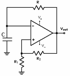
This circuit runs on +9V and -9V which can be supplied by a battery or the Power Supply (HPE3631A). Because of the Capacitor, this whole circuit will bounce between + VCC and –VCC so if +9 and -9 Volts are used, the square wave reaches its peak at +9 and lowest peak at -9V. It remains at either one depending on the voltage level at certain points, and when the capacitor discharges the process is reversed therefore showing a square wave.
The formula that shows the exact period is:
![]()
where the variable ![]() is, using the voltage
divider rule,
is, using the voltage
divider rule,
![]() .
.
How is this equation found?
When the Voltage at the – input on the op amp reaches (z * VCC), then the output switches to –VCC. Now the capacitor is charging to (z * C * VCC) and will then discharge causing the switch to change back to +VCC. The equation for a capacitor that already has an original charge is
![]()
so now substitute ![]() and
and ![]() , giving the final equation for charging time as
, giving the final equation for charging time as
![]()
when q gets to the ![]() voltage level the next
switch occurs and this time is half the period of square wave. So after
substituting for q and solving for T you get:
voltage level the next
switch occurs and this time is half the period of square wave. So after
substituting for q and solving for T you get:
![]() .
.
(Problem #3)
Breadboard the
schematic of the Multivibrator
Use these values first as an Example
(All parts needed should be in cabinet at the back of the lab):
Dual Op-Amp LMC662 or Motorola Quad Op-Amp MC4741C
C = .01 uF
R = 20K
R1 = 20K
R2 = 20K
Set the power supply (HPE3631A) so the 25 Volt range part is used instead of the 6 Volt range. Make sure that there is no short circuit between +9 or –9 and your ground that is the common ground between the 2 sources (+9 and –9). Use the spec sheet for the op Amp to determine which pins are used for what connections are used. Not all the pins will be used (there are 2 op amps combined in the chip).
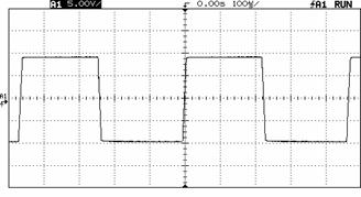
After the circuit is finished, verify that it does show a square or something
close to this.
This lab used the values 20K ohm resistors and .01 uF for the capacitor so the period was:
T = .439 X 10^-3 and Frequency = 2.28 kHz (using approximation when calculating)
which is close to 2 KHz. This should be apparent on the oscilloscope.
(Problem #4)
Briefly explain what
is happening when this circuit is on its negative peak. What is determining how
long the circuit’s output stays high or low? What would happen if the circuit
uses different resistors and capacitors?
If you are having a tough time figuring out #4 then try physically changing the values on your breadboard and look at the output for help.
(Problem #5)
After you have figured out how to change frequencies, add two Light Emitting Diodes or LED’s to this circuit. An led usually doesn’t like any voltage drop over 5 volts so use resistors to lower the voltage for the LED’s and see if you can get them to blink (alternating) :once every second, once every 2 seconds, and then show them blinking twice every second). Record the values of the Resistors or Capacitors used each time and use the formula. Hints:
- use the common ground and the output of the op amp
- LEDs also act as diodes
- if the led is only going to blink and not stay on, then perhaps adding an RC circuit would help but that decision is up to your group
- using both op amps on the chip is acceptable although the less amount of circuitry used the better ( I/O is precious and the less number of pins used, the better)
Deliverables:
1.) A complete breadboarded circuit connected to the oscilloscope.
2.) Show Calculations with explanations for readings on the scope.
(Redraw what you see on the oscilloscope and use that for explanation)
3.) A paragraph or two on the operation of the circuit including answers to questions asked before.
Note: All experiments run and data gathered are to be included in the lab report.
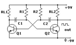
More useful information on Multivibrators…………
The multibvibrator can also be made using Transistors which will be studied in great depth later on in Electronics…. This circuit does exactly what the op amp circuit you just built did.