Networks I - Lab Section 2: Mondays 3.15-6.00 pm
Lab Assignment 1 - due:
next Monday - 18 September 2006
Lab 1 - Hands on Introduction to Breadboards and Ohm’s Law
Objectives: There are three main objectives in this lab. The first objective is to learn the basics of lab equipment and lab safety. The second is to learn the use of a breadboard. A breadboard is a very simple and easy way to make and test circuits. The third objective is to observe Ohm’s law using a breadboard circuit.
Breadboards are useful tools for prototyping and laboratory experiments. They allow for components to be connected together in a semi-permanent fashion. This removes the need to have circuit boards made for every little change in the design.
Basic operation: The 4 outside rows,(1)-(4), are connected horizontally and are usually power and ground. They can be set up any way you feel comfortable.
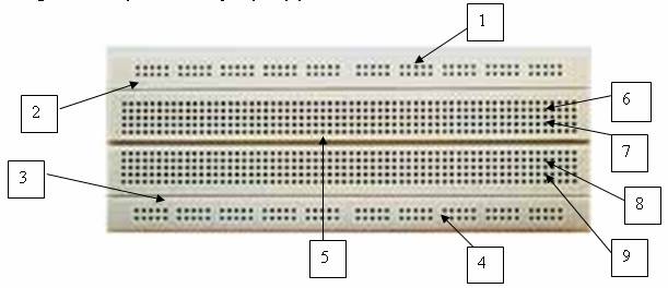
The large line in the middle separates each column.(5) This separates each column into 2 non-connected parts. Pins that are labeled (6) and (7) are connected along with all other pins in that column. Pins labeled (8) and (9) are also connected along with all the other pins in that column. In other words, each column of 5 pins are connected together except for the outer rows that are connected horizontally.
You will be using the Power Supply : Hewlett Packard E3631A and the Multimeter: Keithley 2000 Multimeter.
To use the Power Supply, turn it on, and press the 6+ volt button. Next press the Output on/off button to adjust the voltage. Set the voltage to 5 Volts using the dial and the left and right cursors under the dial. Press the “Output on/off” button in order to turn off the supply.
To use the Multimeter, turn it on and press the voltage button. Acquire two probes from the wall and connect them to the far right connection on the Keithley meter. The red connection is for the positive probe (red), and the black connection is for the negative probe (black).
1. Put together the circuit in Figure 1 to test Ohm’s law. Use R1 = 1 KOhm, R2 = 2 KOhms
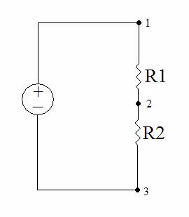
Figure 1: Resistor Circuit
2. Connect the positive terminal of the Power supply to one end of R1 (point 1) and the other end of R1 (point 2) to one end of R2. Next connect the other end of R2 (point 3) to the negative end of the power supply.
3. Press the “Output on/off” button on the power supply. The power supply should be set to 5 volts. Measure the voltage between points 1 and 3, 1 and 2, and 2 and 3 on your circuit and record the results on a table like the one below. (NOTE: Make sure the positive probe is on the positive side of the circuit, and the negative probe is on the negative side of the circuit.)
|
Power Supply Voltage ( V ) |
Voltage between 1 and 3 |
Voltage between 1 and 2 |
Voltage between 2 and 3 |
|
|
|
|
|
|
|
|
|
|
|
|
|
|
|
|
|
|
|
|
|
|
|
|
|
|
|
|
|
|
|
|
|
|
|
4. Repeat this procedure for power supply voltages of 5V, 4V, 3V, 2V and 1V.
5. Next calculate the current through each of the resistors and through both resistors using Ohm’s Law ( V = I*R ) and record your results adding columns to the table and clearly labeling what each column represents. (NOTE: V in Ohm’s law is the voltage across the resistor. The current through R1 would be the voltage measured between points 1 and 2 divided by the value of R1.)
6. Are all the currents the same? Does the current change when the power supply voltage is changed? Explain why or why not.
7. Finally select another resistor (R3) in the 3-10 kOhm range, substitute this resistor for R1 and repeat steps 1-5 above. What can you learn from the mathematical relationship between the voltage changes at point 2 for the different values of resistors?
PART TWO: Complete Mentorgraphics Lab Homework Assignment #2 (note this is to be completed individually and each student must submit there copy of the results of completing the tutorial)
PART THREE: Build the circuit you developed above in Mentorgraphics (describe and compare your results vs. the results you obtained through measurement in the ECE laboratory) At least two students from the Lab team must submit snapshot results of their work.