Homework Given January
23, 2007
Due January 30, 2007
This assignment is due on
Live Links to the Exercises
Exercise 1.1
Use Kirchhoff's Voltage Law in Figure 1.1, page 2, to find
an expression for ![]() in terms of the other
voltages in the circuit.
in terms of the other
voltages in the circuit.
The figure shows a voltage source, ![]() , across Node X and Node Z that drives two voltage
dividers. Loop B in the figure includes
the voltage source and the voltage divider involving
, across Node X and Node Z that drives two voltage
dividers. Loop B in the figure includes
the voltage source and the voltage divider involving ![]() . The loop
equation for
. The loop
equation for
![]() .
.
We solve this equation for ![]() ,
,
![]() .
.
Exercise 1.3
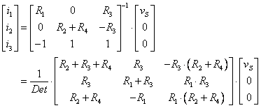
Consider the circuit of Figure P1.3. Write a set of KVL and KCL equations and use
them to find ![]() .
.
We will resist the temptation to use Thevenin and Norton
equivalent circuits to collapse the circuit from the left to find ![]() and then solve the rest
of the circuit to find the voltage at node 1, or to treat the parallel
combination of
and then solve the rest
of the circuit to find the voltage at node 1, or to treat the parallel
combination of ![]() and
and ![]() with
with ![]() as a voltage divider
to find the voltage at node 1 and thence to solve the circuit, etc., because
the problem statement specifically requires that we use KVL and KCL.
as a voltage divider
to find the voltage at node 1 and thence to solve the circuit, etc., because
the problem statement specifically requires that we use KVL and KCL.
We will use the modified figure given below. The values are not included with the resistor names but are given just before the numerical solution below, and signs have been placed on the resistors to show the determination of the signs to be used in designating voltage drops.
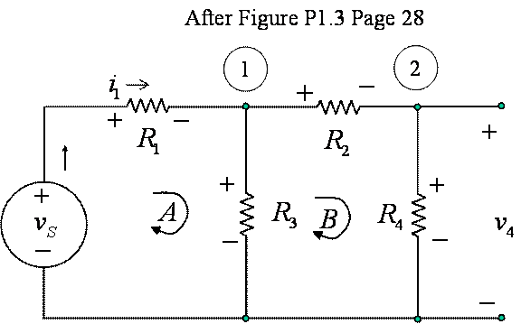
Figure 1 Modified
Figure P1.3 for Analysis using KVL and KCL
We will solve the circuit with a matrix equation, and give
the equation for the voltage ![]() , followed by the numerical solution of the entire
circuit. We begin by writing the KVL
loop equations, followed by the KCL node equations. We use Ohm's Law to obtain equations in the
currents through the resistors. We
conclude with a second look using node voltage notation.
, followed by the numerical solution of the entire
circuit. We begin by writing the KVL
loop equations, followed by the KCL node equations. We use Ohm's Law to obtain equations in the
currents through the resistors. We
conclude with a second look using node voltage notation.

We will simplify our equations to three equations in three unknowns
by noting that ![]() :
:

The solution can be found by Cramer's Rule (substituting the
right hand side vector for the coefficients of ![]() and finding the
determinant, then dividing by the determinant of the unmodified matrix),
Gaussian elimination (adding and subtracting rows to eliminate unknowns until
and finding the
determinant, then dividing by the determinant of the unmodified matrix),
Gaussian elimination (adding and subtracting rows to eliminate unknowns until ![]() is found), using the
TI-89 or other software to solve the entire equation symbolically or
numerically, and other methods. Cramer's
rule is particularly tempting because the right hand side vector has just one
nonzero element, so evaluating the determinants by minors about that column
requires that we evaluate only two by two determinants for the numerator, and
the only three by three determinant is the denominator in common with all three
currents. Here we give the general
solution,
is found), using the
TI-89 or other software to solve the entire equation symbolically or
numerically, and other methods. Cramer's
rule is particularly tempting because the right hand side vector has just one
nonzero element, so evaluating the determinants by minors about that column
requires that we evaluate only two by two determinants for the numerator, and
the only three by three determinant is the denominator in common with all three
currents. Here we give the general
solution,
where ![]() is the determinant of
the matrix,
is the determinant of
the matrix,
 .
.
Note that the determinant cannot be zero unless both ![]() and
and ![]() are zero, i.e. the
source is shorted, which is consistent with the circuit as given. The solution is
are zero, i.e. the
source is shorted, which is consistent with the circuit as given. The solution is

so we have
![]() .
.
The values in the problem statement are given in the figure in the text as

so, numerically, we have

and, with Ohm's law, we have the voltages across the resistors as

We will look at the equations using node voltage notation as a check. Repeating the loop equations,

The matrix form of these equations is

where we have used conductance, the reciprocal of resistance, to save space. The notation is
![]() .
.
The solution is

where ![]() is the determinant of
this matrix,
is the determinant of
this matrix,
![]() .
.
The numerical solution is

which agrees with the previous
solution.
Exercise 1.7
Use KVL for the two loops in the circuit of Figure 1.65(a)
to find a value for ![]() .
.
Figure 1.65(a) is on page 33, and is part of problem 1.65 which is not assigned here. The two loops are both counterclockwise. The loop equations are
![]()
Note that we used ![]() as the voltage across
the controlled current source. Also,
note that the there are two resistors denoted
as the voltage across
the controlled current source. Also,
note that the there are two resistors denoted ![]() in the circuit of
Figure 1.65(a).
in the circuit of
Figure 1.65(a).
Since
![]() , all we need is
, all we need is ![]() , which we can get from the first loop:
, which we can get from the first loop:
![]() ,
,
which is seen to be a straightforward application of Ohm's law. Combining these equations we have
![]() .
.
The circuit is a simplified model of a FET transistor, and ![]() is the transconductance of the transistor – the
ratio of current out to voltage input, and has the physical units of conductance,
or reciprocal ohms.
is the transconductance of the transistor – the
ratio of current out to voltage input, and has the physical units of conductance,
or reciprocal ohms.