Electronics I Laboratory 3
Today we will complete the first-cut audio amplifier and measure the v-i curve for a diode.
Navigation
![]() Two Op-Amp Amplifier with Complementary
Transistor Driver
Two Op-Amp Amplifier with Complementary
Transistor Driver
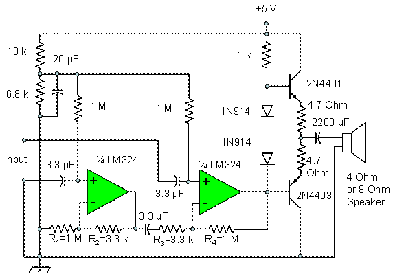
![]() Schematic of Two Op-Amp Differential Driver Circuit
with Complementary Output
Schematic of Two Op-Amp Differential Driver Circuit
with Complementary Output
![]() Schematic of Diode v-i Curve Test Circuit
Schematic of Diode v-i Curve Test Circuit
![]() Report Instructions for Two Op-Amp Amplifier
with Complementary Transistor Driver
Report Instructions for Two Op-Amp Amplifier
with Complementary Transistor Driver
![]() Report Instructions for Diode v-i Curve
Experiment
Report Instructions for Diode v-i Curve
Experiment
Two Op-Amp Amplifier with Complementary Transistor Driver
Tasks for this experiment:
![]() Beginning
with the Complementary Transistor Driver circuit form Laboratory 2, add the two
op-amp driver circuit to make up a complete circuit as shown below as Figure 1. Replace the
Beginning
with the Complementary Transistor Driver circuit form Laboratory 2, add the two
op-amp driver circuit to make up a complete circuit as shown below as Figure 1. Replace the ![]() capacitor and speaker
at the output with a
capacitor and speaker
at the output with a ![]() capacitor and a
capacitor and a ![]() load for today's laboratory. If you used 2N3904/2N3906 instead of
2N4401/2N4403, leave your transistors as placed in the circuit for this
laboratory. You may be given an LM358, a
dual op-amp, instead of an LM324, a quad op-amp. If you get an LM324, ask the Instructor how
to hook up the unused op-amps.
load for today's laboratory. If you used 2N3904/2N3906 instead of
2N4401/2N4403, leave your transistors as placed in the circuit for this
laboratory. You may be given an LM358, a
dual op-amp, instead of an LM324, a quad op-amp. If you get an LM324, ask the Instructor how
to hook up the unused op-amps.
![]() Measurements
of voltage that assure that the circuit is working are given below in the
report instructions. Make these
measurements after your circuit is working and record them for your report.
Measurements
of voltage that assure that the circuit is working are given below in the
report instructions. Make these
measurements after your circuit is working and record them for your report.
![]() Set
up your signal generator for a sine wave output
Set
up your signal generator for a sine wave output
![]() Amplitude
1 millivolt peak
Amplitude
1 millivolt peak
![]() Frequency
1,000 Hz
Frequency
1,000 Hz
![]() Apply
the amplifier and signal generator output to the oscilloscope. The amplifier output is the voltage across
the
Apply
the amplifier and signal generator output to the oscilloscope. The amplifier output is the voltage across
the ![]() load. Adjust the signal generator output as
necessary to provide as large a s possible signal at the output without visible
distortion. Measure the voltage gain of
the circuit.
load. Adjust the signal generator output as
necessary to provide as large a s possible signal at the output without visible
distortion. Measure the voltage gain of
the circuit.
![]() Save
the plots for your lab report
Save
the plots for your lab report
![]() Repeat
for a 1 millivolt peak triangular wave at 1,000 Hz.
Repeat
for a 1 millivolt peak triangular wave at 1,000 Hz.
![]() Repeat
for a 1 millivolt peak square wave at 1,000 Hz.
Repeat
for a 1 millivolt peak square wave at 1,000 Hz.
![]() Change
the frequency of the signal generator to find the high and low frequency limits
over which the output amplitude remains approximately constant. Write down the frequencies for which the
amplitude of the output is 0.7 times the amplitude at 1000 Hz. These are the 3 dB points in the frequency
response.
Change
the frequency of the signal generator to find the high and low frequency limits
over which the output amplitude remains approximately constant. Write down the frequencies for which the
amplitude of the output is 0.7 times the amplitude at 1000 Hz. These are the 3 dB points in the frequency
response.
Schematic of Two Op-Amp Differential Driver Circuit with Complementary Output
Note that this circuit is a circuit involving two op-amps, added to the circuit built for Laboratory 1. Leave the circuit for Laboratory 3 on the wireless prototype board because you will be using it when we discuss biasing of three-terminal devices and for other experiments.
Figure
1. Completed
First-Cut Audio Amplifier
Diode v-i Curve Experiment
![]() Construct
the circuit consisting of a
Construct
the circuit consisting of a ![]() resistor in series
with a diode as shown in Figure
2. While the
resistor is not connected to the power supply, measure its resistance with your
multimeter to the highest accuracy possible with the instrument. Record this resistance for use in finding
currents, and for your report.
resistor in series
with a diode as shown in Figure
2. While the
resistor is not connected to the power supply, measure its resistance with your
multimeter to the highest accuracy possible with the instrument. Record this resistance for use in finding
currents, and for your report.
![]() Adjust
your power supply for voltages between 0 V and 6 V and measure the voltage and
current through the diode. Measure the
current by connecting your multimeter across the resistor and recording the
voltage drop, then divide by the resistance that you measured. Note that the ground of the multimeter must
be floating, not connected to bench ground, for this measurement. Use, as a minimum, the voltages shown in Table 1.
Adjust
your power supply for voltages between 0 V and 6 V and measure the voltage and
current through the diode. Measure the
current by connecting your multimeter across the resistor and recording the
voltage drop, then divide by the resistance that you measured. Note that the ground of the multimeter must
be floating, not connected to bench ground, for this measurement. Use, as a minimum, the voltages shown in Table 1.
Table 1. Voltages to be Applied to Diode v-i Test Circuit. Measurements to be Taken are Diode Voltage and Current.
|
Power
Supply voltage |
Diode
Voltage |
Diode
Current |
|
0.1 Volts |
|
|
|
0.2 Volts |
|
|
|
0.3 Volts |
|
|
|
0.4 Volts |
|
|
|
0.5 Volts |
|
|
|
0.6 Volts |
|
|
|
0.7 Volts |
|
|
|
0.8 Volts |
|
|
|
0.9 Volts |
|
|
|
1.0 Volts |
|
|
|
1.5 Volts |
|
|
|
2.0 Volts |
|
|
|
2.5 Volts |
|
|
|
3.0 Volts |
|
|
|
3.5 Volts |
|
|
|
4.0 Volts |
|
|
|
4.5 Volts |
|
|
|
5.0 Volts |
|
|
|
5.5 Volts |
|
|
|
6.0 Volts |
|
|
Schematic of Diode v-i Curve Test Circuit
This is a simple circuit for measuring the voltage and current through a diode, and varying it over input currents up to about 5 milliamperes. Make sure that your diode is inserted with the cathode to ground. Check by applying about 2 Volts to the circuit and checking the output voltage; if the output voltage is about 2 volts, reverse the diode.
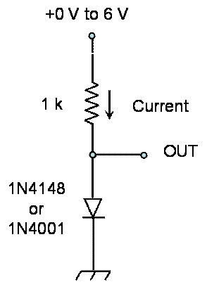
Figure
2 Circuit for Measuring Diode v-i Curve
Instructions for your Report
Use the instructions given on this link. The lab report is due one week from today. Submit your report as a file by e-mail to no_spam_jkbeard@jameskbeard.com.
Report Instructions for Two Op-Amp Amplifier with Complementary Transistor Driver
![]() Measure
the DC voltage at the voltage divider at the top left of the circuit. This voltage divider is a
Measure
the DC voltage at the voltage divider at the top left of the circuit. This voltage divider is a ![]() and a
and a ![]() resistor in series,
with a
resistor in series,
with a ![]() capacitor bypassing
the
capacitor bypassing
the ![]() resistor. This voltage should be about 2.02 Volts. This is your circuit reference voltage.
resistor. This voltage should be about 2.02 Volts. This is your circuit reference voltage.
![]() Measure
the DC voltage at the inverting inputs to both op-amps. Both should be the same as that of the
voltage divider. In your report, explain
why this is so.
Measure
the DC voltage at the inverting inputs to both op-amps. Both should be the same as that of the
voltage divider. In your report, explain
why this is so.
![]() Measure
the voltage at the output of the left op-amp in the circuit. It should be slightly more than the circuit
reference voltage. Explain why in your
report.
Measure
the voltage at the output of the left op-amp in the circuit. It should be slightly more than the circuit
reference voltage. Explain why in your
report.
![]() The
first op-amp we define here is the leftmost in the schematic. This op-amp is a non-inverting amplifier for
the input at the lower of the two input terminals. Find the gain of this non-inverting amplifier
as a function of the two resistors
The
first op-amp we define here is the leftmost in the schematic. This op-amp is a non-inverting amplifier for
the input at the lower of the two input terminals. Find the gain of this non-inverting amplifier
as a function of the two resistors ![]() and
and ![]() on the first op-amp, up to the
on the first op-amp, up to the ![]() coupling capacitor.
coupling capacitor.
![]() The
second op-amp we define here is the rightmost in the schematic. To the signal from the first op-amp, this is
an inverting amplifier. Find the gain of
this inverting amplifier as a function of the two resistors
The
second op-amp we define here is the rightmost in the schematic. To the signal from the first op-amp, this is
an inverting amplifier. Find the gain of
this inverting amplifier as a function of the two resistors ![]() and
and ![]() in this op-amp
circuit.
in this op-amp
circuit.
![]() The
first op-amp circuit is a non-inverting amplifier for the upper of the two
input terminals. Find th gain of this
non-inverting amplifier as a function of the two resistors
The
first op-amp circuit is a non-inverting amplifier for the upper of the two
input terminals. Find th gain of this
non-inverting amplifier as a function of the two resistors ![]() and
and ![]() in this op-amp
circuit.
in this op-amp
circuit.
![]() Show
that if
Show
that if ![]() and
and ![]() , then the output of the second op-amp is a gain factor times
the difference between the voltages at the input terminals. Find this gain factor in terms of
, then the output of the second op-amp is a gain factor times
the difference between the voltages at the input terminals. Find this gain factor in terms of ![]() and
and ![]() . Give the
relationship between the values of the resistors
. Give the
relationship between the values of the resistors ![]() ,
, ![]() ,
, ![]() and
and ![]() that is required for
the two op-amp circuits together to be a differential amplifier.
that is required for
the two op-amp circuits together to be a differential amplifier.
![]() Note
that we are using 5% tolerance for the resistors
Note
that we are using 5% tolerance for the resistors ![]() ,
, ![]() ,
, ![]() and
and ![]() , so we cannot expect for the differential gain to be
exact. The difference between the gains
is called the common mode gain. Measure the common mode gain by connecting
the two input terminals together and applying a 1000 Hz sine wave voltage to
them with the signal generator. Apply up
to 2.5 volts peak to get a measurable signal on the output, across the
, so we cannot expect for the differential gain to be
exact. The difference between the gains
is called the common mode gain. Measure the common mode gain by connecting
the two input terminals together and applying a 1000 Hz sine wave voltage to
them with the signal generator. Apply up
to 2.5 volts peak to get a measurable signal on the output, across the ![]() load. Note that you measured the gain of the
circuit as part of the experiment; this is the differential gain. Compare the common mode gain with the
differential gain. Give the difference
as a voltage ratio and as a figure in dB.
load. Note that you measured the gain of the
circuit as part of the experiment; this is the differential gain. Compare the common mode gain with the
differential gain. Give the difference
as a voltage ratio and as a figure in dB.
Report Instructions for Diode v-i Curve Experiment
![]() Plot
the diode v-i curve from the data you took in the experiment.
Plot
the diode v-i curve from the data you took in the experiment.
![]() Compare
the v-i curve with a theoretical curve using the equation
Compare
the v-i curve with a theoretical curve using the equation

where

![]() Will
changing the values of
Will
changing the values of ![]() and
and ![]() give you better
agreement? What are these values? Note that more data at the point where the
current begins to flow can be helpful here.
Also, the v-i curve equation can be manipulated to give a form that may
be better in understanding the roles of
give you better
agreement? What are these values? Note that more data at the point where the
current begins to flow can be helpful here.
Also, the v-i curve equation can be manipulated to give a form that may
be better in understanding the roles of ![]() and
and ![]() in the v-i curve.
in the v-i curve.
